I have made a couple of clock project in the past. I have always used DS1306 module to do it. I received the backlash from my viewers. They questioned why I would use that particuler RTC module labeling it as not relaible. Now that I think of it I had issues with those RTC modules being off by a minute or two after operating for a week. Everyone pointed to DS3231 as a much more precise module. I thought to myself : "I have to give it a try". Show
So here is a tutorial how to build cool looking clock using Arduino, DS3231 and OLED display. Step 1: DS3231 RTC ModuleThe DS3231 is a low-cost, extremely accurate I2C real- time clock (RTC) with an integrated temperature sensor. The device has a battery input, and maintains accurate timekeeping when main power to the device is interupted Step 2: Connecting DS3231 to ArduinoFinally the project where the connectivity is super simple. To connect this RTC module to Arduino we need to:
We have to use exactly those pins as they are meant for I2C comunication. Step 3: Writing Simple Code to Display TimeBefore we look at the code we need to import DS3231 library. There are a few of them available on Github. Here is the link to the library I am going to use. DS3231 Library To get it in you need to download the zip file. Then open this zip file in Arduino IDE. With each library come some example sketches and this one is no different. As you can see there are few of them. Now to the code . Lets create the simplest scetch to display date and time in the most basic format. We start with declaring the libraries. include <Wire.h><br>include <DS3231.h>First one enables us to use I2C comunication and the second one is the one we just installed which will help us with controlling RTC module. The we declare the RTC module and also we declare the of RTCDateTime object . DS3231 clock;<br>RTCDateTime dt; RTCDateTime type consists of following components .
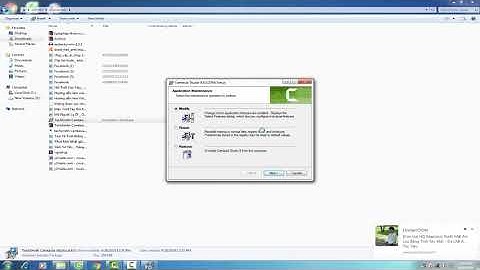
In setup function we open serial monitor to be able to see the scetch results and then we initiate the RTC module. And finally we set the time to the time the scetch was compiled at. That is very handy functionality which makes setting up current time on the RTC very easy void setup() { Serial.begin(9600); clock.begin(); // Set sketch compiling time clock.setDateTime( DATE , TIME ); In the main loop we run clock.getDateTime() time method to read current date and time to the dt object we have previously defined. And then with print function we output the time serial monitor. As you can see the format is very basic. You do not see the leading zeros where they should be so if you wanted to output date in time in the other way there would still be some string operations required. void loop(){ dt = clock.getDateTime(); Serial.print(dt.year); Serial.print("-"); Serial.print(dt.month); Serial.print("-"); Serial.print(dt.day); Serial.print(" "); Serial.print(dt.hour); Serial.print(":"); Serial.print(dt.minute); Serial.print(":"); Serial.print(dt.second); Serial.println(""); delay(1000); } Step 4: Reading Temperature With DS3231The DS3231 RTC has a built-in temperature sensor with a resolution of 0.25 and an accuracy of ±3°C . The temperature registers are updated after every 64-second conversion. If you want force temperature conversion use forceConversion() So if you want to display temperature in the main loop you have to add following lines of code clock.forceConversion(); Serial.print("Temperature: "); <br>Serial.println(clock.readTemperature()); Step 5: Adding OLED Display Into the ProjectNow that we know how to controle this type or rtc module lets move away from serial monitor and try to display time on the small OLED display. When I wanted to connect it to arduino I realised that it also needs to be connected via pins A4 and A5 as this OLED display is also an I2C device. So what now. Those pins are already taken. You have to realise that those pins are not dedicated to any particular device. They can be shared accross many devices as they connect those devices to I2c bus. So for starters lets connect VCC and ground of the oled display to arduino Then lets envisage the I2C bus with the Serial Data line called SDA in short and Serial Clock line called SCL. Arduino is connected to that bus via analog pin a4 to SDA and via analog pin A5 to SCL. Microcontroller is a master device. The way of Connecting to I2C bus may differ depending on which arduino board you use. e.g in Uno A4 And A5 pins would work but there are also dedicated I2C ports. In Arduino Mega on the other hand A4 and A5 cannot be used for that purpose. So check the documentation of the board you are planning to use. Now we can connect the rtc module to that bus as a slave and OLED display in the same way as a second slave device. Ok. But how would Arduino recognise which device is which to communicate with it. Each device have its unique address. So DS3231 RTC module should be avaiable at 68hex address while OLED display should be at 3C hex. If however you come accross issues while connecting any of the commponents you can use I2c scanner sketch to detect all avaialble devices connected to the bus and their addresses. Here is the url you can find a I2C scanner sketch. https://playground.arduino.cc/Main/I2cScanner/ Paste it to the arduino IDE and execute it. For my little set up the I2c scanner detects following devices (see attached screenshot) Step 6: Custom Functions Needed to Display Time in a Proper Format.We need to write following function to be able to format the output the values read from RTC module into desired date and time format:
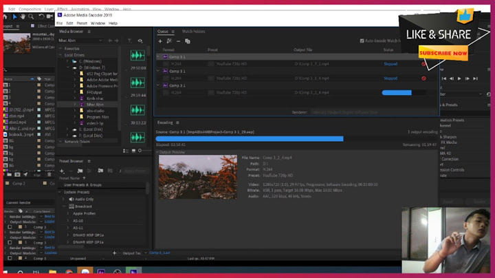
Step 7: Code to Display Time on the OLED DisplayHaving custom functions in place we can write a code that will display date and time in desired format on the oled display. We require two more libraries for controling the display include <Adafruit_GFX.h>include <Adafruit_SSD1306.h>Then we define its dimentions. And decalre the display itself define SCREEN_WIDTH 128 // OLED display width, in pixelsdefine SCREEN_HEIGHT 64 // OLED display height, in pixelsdefine OLED_RESET -1 // Reset pin # (or -1 if sharing Arduino reset pin)Adafruit_SSD1306 display(SCREEN_WIDTH, SCREEN_HEIGHT, &Wire, OLED_RESET); In setup function we add a section which checks if display properly initialised. It halts sketch execution if display is not detected. if(!display.begin(SSD1306_SWITCHCAPVCC, 0x3C)) { // Address 0x3D for 128x64 Now lets look at the code of the main loop to transform reading from the RTC module to graphical representation of date and time First we save the reading from the RTC to the dt object dt = clock.getDateTime(); Then we draw three rectanglers/panels. First in white and since this particular display is dual color one where first 15 lines are yellow it shows in yellow. Then we draw another one in black and then another one in white which will show in blue as that part of the display is blue. (as shown on the photo) display.fillRect(0,0,128,16,SSD1306_WHITE); display.fillRect(0,17,128,16,SSD1306_BLACK); display.fillRect(0,31,128,33,SSD1306_WHITE); Then after selecting cursor position and font color and size we output full day of the week in top panel using DayOfTheWeek function. DS3231 clock;<br>RTCDateTime dt; 0 We continue with displaying Short name of the month day of the month and a full year in middle panel using DayMonthYear function DS3231 clock;<br>RTCDateTime dt; 1 We can also add temperature into top panel as well. DS3231 clock;<br>RTCDateTime dt; 2 In main panel we display hours and minutes using CurrentTime function and then with the smaller font we are also displaying seconds. DS3231 clock;<br>RTCDateTime dt; 3 We ended up with fairly nice looking design of the clock. Step 8: Problematic DateFormat FunctionThe library I am using in this tutorial provide one extra function called DateFormat. This is a powerful function which helps us to format the time/date read of the RTC module anyway we want easy and without the need of writing additional functions like we did in our code. I am providing syntax of this function here with examples. There is a problem with that function though. It requires a lot of memory and if you coose to use it with OLED display your sketch would run out of memory. This problem was reported to library creator, but it seems he has stopped working on this library, and this problem may never be fixed. You can still use this function with arduino compatible microcontrollers thathave more than 2k of Sram (Arduino Mega, Bluepill etc). I will provide in the closing chapter a link to the code that is using this DateFormat format to achieve the same result as our code here, and you will see that this greatly simplifies the code. Step 9: ConclusionThank you for spending time reading through this tutorial. I stronglt encourage you to watch the Youtube video at the beginnig of this tutorial which shows the code creation and you can see the final result. If you find this tutorial useful please give this youtube video a like. It helps me to create similar content. Here you will find link to the code: Link to the code If you like this content and you want to support me in creating similar videos go to my Patreon webpage https://www.patreon.com/MariosIdeas Or Paypal |